
Page 73 - Visual Guidance Handbook
P. 73
Let’s all
STEEL MESH BARRIER SYSTEMS get home safely,
every day
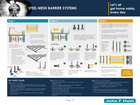
Stage 1 Stage 2 Stage 3
▪ KGuard & Combisafe use different posts that are
not interchangeable. The post must be located
between No2 dimples and then twisted to lock the
post into the socket.
▪ Combisafe has a spring loaded ball catch that
secures the post. KGuard barriers are secured
by the latches on the post.
• Install from a safe location i.e. ▪ Install KGuard or Combisafe socket bases by drilling ▪ KGuard barriers are secured by the latches on the
from below or using Alsipercha and installing an expansion bolt into the slab. post. Ensure that the post is correctly seated into
or Leading Edge fall restraint Combisafe sockets require a standard M16 65mm the socket so that the bottom of the barrier is no
line. bolt whereas KGuard uses a double ended stud bolt. more than 15mm of the slab.
• Install KGuard or Combisafe These are not interchangeable.
Aluma beam clamps at right POST INSERTION EMPTY
angles to the face of the barrier. SOCKET
SOCKET BASES ▪ Safety Post
A TYPICAL SCHEME insertion into INSERTPOST
Note the positioning of the 1 2 3 socket and WITHSPIGOTS
INLINEWITH
two clamp types. 20mm 200mm rotation to SINGLEINDENT
PRIMARYALUMINIUM engage
BEAMCLAMP
• Standard beam clamps STANDARD ALUMINIUM 70mm K-Lock Safety
BEAM CLAMP
cannot be used on all SECONDARYBEAM system. ROTATE POSTTO
ACTIVATEK-LOCK
edges because aluminium PRIMARYBEAM Only install into full strength fully SAFETY SYSTEM
beams do not provide the cured, mature, sound concrete Insert the M16 anchor. The Anchors must be set using
required strength when used surfaces. Drill a 20mm hole, 70mm anchor must sit flush with setting tool. Hammer until
as shown. the slab surface and not sit solid resistance is felt. This
• Barriers fitted to these deep no less than 200mm from above. If the anchor sits secures the anchor into the
the slab edge. Ensure that sharpe,
incorrect clamp points well maintained drill bits are proud, check the hole sizes concrete. Anchor will not
would not support the used [image 1]. and check for debris in the secure if not correctly set
[image 3].
required loading. Aluminium hole [image 2].
beams are very flexible in
this direction. Always use the 4 5 6
primary beam clamps.
CLAMP TYPES INSTALLATION OF SAFETY BARRIER INTO POSTS
INSUFFICIENTSTRENGTH The socket base studs should be Thread the socket base into the Tighten the socket base with ▪ Place Barrier onto spigots then
STANDARD fitted as shown. The longer secure by locking latches into the
ALUMINIUM Note: Ensure formwork threated portion fits into the base. anchor until the foot is the KGuard spanner [image 6]. vertical position. REPORT
BEAM CLAMP has been correctly assembled to touching the concrete
ALUMA BEAMS Note: If the anchor is installed ALL FAULTS
CLAMP manufactures specification and all below the surface then the stud [image5]. ▪ Ensure Barrier is installed with the
PRIMARY beams are correctly assembled together. can be reversed [image 4]. logo side facing toward the posts.
ALUMINIUM
BEAMS CLAMP
KEY SAFETY ISSUES Stage 2: Fixing to concreteslab Stage 3: Placement of posts andbarriers
▪ Be aware of any slab details such as post-tensioned tendons prior to ▪ Working at Height-fall prevention - Operatives erecting edge protection must
Stage 1: Fixing to Aluma Beams drilling into the slab. wear suitable fall protection gear and be trained in itsuse.
▪ Consideration must be given when erecting the deck to the location of the ▪ On slabs, plot out the location of the posts prior to installation to ▪ Post must be fully engaged to the socket prior to fitting barrier.
beam clamps. Sufficient space must be left for the clamp to be located at a account for corners and radius elements. ▪ Barriers must be secured using latches rather than
right angle to the leading edge.
▪ Working at Height-fall prevention using Alsipercha or Fall restraint - Operatives ▪ Ensure the correct bolt is used for the combisafe socket (M16 bolt) and tying wire.
KGuard socket (double ended stud).
erecting edge protection must wear suitable fall protection gear and be ▪ Where beam clamps or sockets cannot be installed to provide a post and
trained in its use. ▪ Anchor must be set using setting tool. secure anchor for the barrier, tying wire must be used at 300mmcentres.
▪ The area below must also be cordoned off to prevent people walking ▪ Ensure the socket is flush with theslab. ▪ Where tying wire is used, consider placing warning signs to preventremoval.
below the works. ▪ Install edge protection to slab prior to removing falsework edge
protection.
Page 73